


Imaging Electronics 101: Basics of Digital Camera Settings for Improved Imaging Results
Digital cameras, compared to their analog counterparts, offer greater flexibility in allowing the user to adjust camera settings through acquisition software. In some cases, the settings in analog cameras can be adjusted through hardware such as dual in-line package (DIP) switches or RS-232 connections. Nevertheless, the flexibility of modifying settings through the software greatly adds to increased image quality, speed, and contrast - factors that could mean the difference between observing a defect and missing it altogether. Many digital cameras have on board field-programmable gate arrays (FPGAs) for digital signal processing and camera functions. FPGAs perform the calculations behind many digital camera functions, as well as additional ones such as color interpolation for mosaic filters and simple image processing (in the case of smart cameras). Camera firmware encompasses the FPGA and on board memory; firmware updates are occasionally available for cameras, adding and improving features. The on board memory in digital cameras allows for storage of settings, look up tables, buffering for high transfer rates, and multi-camera networking with ethernet switches. Some of the most common digital camera settings are gain, gamma, area of interest, binning/subsampling, pixel clock, offset, and triggering. Understanding these basic settings will help to achieve the best results for a range of applications.
GAIN
Gain is a digital camera setting that controls the amplification of the signal from the camera sensor. It should be noted that this amplifies the whole signal, including any associated background noise. Most cameras have automatic gain, or autogain, which is abbreviated as AGC. Some allow the user to turn it off or set it manually.
Gain can be before or after the analog-to-digital converter (ADC). However, it is important to note that gain after the ADC is not true gain, but rather digital gain. Digital gain uses a look up table to map the digital values to other values, losing some information in the process.
Gain before the ADC can be useful for taking full advantage of the bit-depth of the camera in low light conditions, although it is almost always the case that careful lighting is more desirable. Gain can also be used to ensure that the taps of multi-tap sensors are well matched. For a detailed discussion of sensor taps, view Imaging Electronics 101: Camera Resolution for Improved Imaging System Performance. In general, gain should be used only after optimizing the exposure setting, and then only after exposure time is set to its maximum for a given frame rate. To visually see the improvement gain can make in an image, compare Figures 1a, 1b, 2a, and 2b.

Figure 1a: Real-World Image without Gain (AGC = 0), Gamma = 1, 8MHz Pixel Clock, and 0.2ms Exposure

Figure 1b: Close-Up of Image with AGC = 0, Gamma = 1, 8Hz Pixel Clock, and 0.2ms Exposure
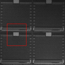
Figure 2a: Real-World Image with High Gain (AGC = 100), Gamma = 1, 8MHz Pixel Clock, and 3.4ms Exposure

Figure 2b: Close-Up of Image with AGC = 100, Gamma = 1, 8MHz Pixel Clock, and 3.4ms Exposure
GAMMA
Gamma is a digital camera setting that controls the grayscale reproduced on the image. An image gamma of unity (Figures 3a - 3b) indicates that the camera sensor is precisely reproducing the object grayscale (linear response). A gamma setting much greater than unity results in a silhouetted image in black and white (Figures 4a – 4b). In Figure 4b, notice the decreased contrast compared to Figure 3b. Gamma can be thought of as the ability to stretch one side (either black or white) of the dynamic range of the pixel. This control is often used in signal processing to raise the signal-to-noise ratio (SNR).

Figure 3a: Real-World Image with Gamma Equal to Unity (Gamma = 1), 10MHz Pixel Clock, and 5ms Exposure
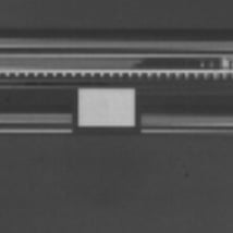
Figure 3b: Close-Up of Image with Gamma = 1, 10MHz Pixel Clock, and 5ms Exposure

Figure 4a: Real-World Image with Gamma Greater than Unity (Gamma = 2), 10MHz Pixel Clock, and 5ms Exposure

Figure 4b: Close-Up of Image with Gamma = 2, 10MH Pixel Clock, and 5ms Exposure
AREA OF INTEREST
Area of interest is a digital camera setting, either through software or on board, that allows for a subset of the camera sensor array to be read out for each field. This is useful for reducing the field of view (FOV) or resolution to the lowest required rate in order to decrease the amount of data transferred, thereby increasing the possible frame rate. The full resolution, in terms of Nyquist frequency or spatial sampling frequency, can be retained for this subset of the overall field. For example, a square field of 494 x 494 may contain all of the useful information for a given frame and can be used so as to not waste bandwidth. For additional information on Nyquist frequency, view Imaging Electronics 101: Camera Types and Interfaces for Machine Vision Applications.
BINNING/SUBSAMPLING
With binning or subsampling, the entire FOV is desired, but the full camera resolution may not be required. In this case, the gray value of adjacent pixels can be averaged together to form larger effective pixels, or only every other pixel read out. Binning or subsampling increases speed by decreasing the amount of data transferred.
Binning is specific to CCD sensors, where the charge from adjacent pixels are physically added together, increasing the effective exposure and sensitivity. Subsampling generally refers to CMOS sensors, where binning is not strictly possible; subsampling offers no increase in exposure or sensitivity. Subsampling can also be used with CCD sensors in lieu of binning when low resolution and high transfer rates are desired without the desire for the original exposure. For in-depth information on sensors, view Imaging Electronics 101: Understanding Camera Sensors for Machine Vision Applications.

Figure 5: Illustration of Camera Pixel Binning or Subsampling
PIXEL CLOCK
In a CCD camera sensor, the pixel clock describes the speed of the complementary signals which are used to move the charge packets through the shift registers towards the read out amplifiers. This determines how long it takes to read out the entire sensor, but it is also limited by noise and spillover issues which occur when the packets are transferred too quickly. For example, two cameras with identical sensors may use different pixel clock rates, leading to different performances in saturation capacity (linear range) and frame rate. This setting is not readily user adjustable, as it is generally set to an optimal value specific to the sensor and FPGA capabilities. Overclocking a sensor by increasing the pixel clock can also lead to thermal issues.
OFFSET
Offset refers to the DC component of a video or image signal, and effectively sets the black level of the image. The black level is the pixel level (in electrons, or volts) which corresponds to a pixel value of zero. This is often used with a histogram to ensure the full use of the camera bit-depth, effectively raising signal-to-noise. Pushing non-black pixels to zero lightens the image, although it gives no improvement in the data. By increasing the black level, offset is used as a simple machine vision image processing technique for brightening and effectively creating a threshold (setting all pixels below a certain value to zero to highlight features) for blob detection.
TRIGGERING
Depending upon the application, it can be useful to expose or activate pixels only when an event of interest occurs. In this case, the user can use the digital camera setting of trigger to make the camera acquire images only when a command is given. This can be used to synchronize image capture with a strobed light source, or take an image when an object passes a certain point or activates a proximity switch, the latter being useful in situations where images are being stored for review at a later time. Trigger can also be used in occasions when a user needs to take a sequence of images in a non-periodic fashion, such as with a constant frame rate.
Triggering can be done through hardware or software. Hardware triggers are ideal for high precision applications, where the latency intrinsic to a software trigger is unacceptable (which can be many milliseconds). Software triggers are often easier to implement because they take the form of a computer command sent through the normal communication path. An example of a software trigger is the snap function in image viewing software.
Though a host of additional digital camera settings exist, it is important to understand the basics of gain, gamma, area of interest, binning/subsampling, pixel clock, offset, and trigger. These functions lay the groundwork for advanced image processing techniques that require knowledge of the aforementioned basic settings. To learn more about imaging electronics, view our additional imaging electronics 101 series pertaining to camera sensors, camera resolution, and camera types.

or view regional numbers
QUOTE TOOL
enter stock numbers to begin
Copyright 2023, Edmund Optics Inc., 18 Woodlands Loop #04-00, Singapore 738100
California Consumer Privacy Act (CCPA): Do Not Sell or Share My Personal Information
California Transparency in Supply Chains Act