


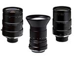
Lens Spacers, Shims, and Focal Length Extenders
This is Section 5.2 of the Imaging Resource Guide.
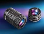
Applications can require a lens to stretch beyond its limits or be precisely dialed-in to its ideal design parameters. Lens spacers, shims, and focal length extenders are simple tools a user can easily use to achieve these requirements. These tools are used in between the lens and lens mount on the camera. Spacers and focal length extenders modify field of view (FOV) or working distance (WD) in fixed focal length lenses, whereas shims can be used to precisely control the WD of telecentric lenses.
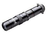
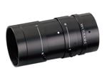
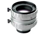
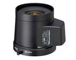
Lens Spacers
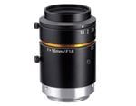
Most fixed focal length lenses have integrated mechanics to focus on different WDs. The fixed focal length nature of the design means that the elements move throughout a defined range (and do not move relative to one another), which dictates the WDs where the focus is achievable. This predefined range is chosen based on the design of the lens. However, it is often advantageous to stretch a lens beyond its limits to fit an application where smaller FOVs or shorter WDs are required. Augmenting the system with a spacer between the camera and lens changes the range of WDs over which the lens performs optimally.
The main purpose of adding a spacer is to increase the vision system’s magnification or shorten the WD; these two changes occur in tandem and are explained by the Gaussian imaging equations.
Equation 1 shows the relationship between the image distance $ \small{ \left( d \right) }$ and the focal length of the lens $ \small{ \left( f \right) }$ . By increasing the image distance, the WD must decrease. When the WD and image distance change, so must the magnification $ \small{ \left( m \right) }$ , based on Equation 2 (see Contrast for more information on magnification). Figure 1 shows this effect visually. Imaging lenses are more complex systems and the calculations for spacer usage are more complicated.
The decrease in WD and the increase in magnification (reduction of the FOV) are the two most distinctive advantages of using a spacer. Choosing the correct spacer will vary by application but consider an example with a 35mm focal length lens compared to the same 35mm lens with an 11mm spacer. The result of the spacer can be found in Table 1. The spacer in the example has the most significant impact on the WD, which is reduced by more than half, and the magnification which more than doubles. This type of spacer also has advantages for space-constrained systems as the total track length (length from the image plane to the object plane) is reduced.
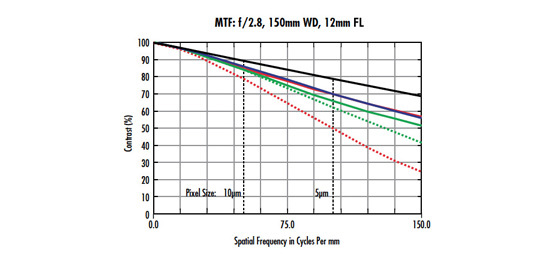
It is also important to consider the performance impact spacers have on the optical system. The WD range over which the lens physically operates before adding the spacers is generally where the best performance will be, based on the optical design, and performance will typically suffer as these distances are altered with spacers. Figures 2 and 3 show the modulation transfer function (MTF) curves for the lens from the example above at f/4 and on a 2/3” sensor, at the minimum WD and with the 11mm spacer, respectively. As a rule of thumb, a spacer should not be used if it is more than half of the focal length. If used correctly, spacers can be an excellent way to adapt a lens to a specific application, as long as the limitations and performance impacts are fully considered. Making illumination monochromatic will help mitigate these performance issues. Using a lens within its design range is the best option for optimal performance. Longer focal length lenses tend to respond better to spacers, as they are often simpler designs compared to shorter focal length lenses.

Figure 1: An illustration of the relationship between image distance, WD, and focal length.
| No Spacers | 11mm Spacer | |
|---|---|---|
| Focal Length | 35mm | 35mm |
| Lens Length | 41mm | 52mm |
| Image Distance | 42.9mm | 53.9mm |
| Working Distance | 165 | 74.1 |
| Total Track | 223.5 | 143.6 |
| Magnification | 0.22X | 0.54X |
| Field of View (½") | 28.5mm | 11.88mm |
Table 1: Comparison of specifications of the same 35mm focal length lens (focused at minimum WD) with and without a spacer. The most important changes are bolded.

Figure 2: 35mm focal length lens at the minimum designed WD.

Figure 3: 35mm focal length lens with 11mm spacer.
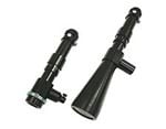
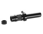
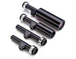
Shims
Shims follow the same basic concept as spacers but are used for fixed magnification lenses such as telecentric lenses. Shims are thin (0.025 - 1.0mm) stainless steel spacers used to control WD with fine precision to guarantee the best image quality. Flange distance can vary slightly from the nominal design because of tolerancing in the housing design or the sensor placement; as such, shims may be used as thin spacers between the lens and camera to customize and correct for this deviation.
As image distance varies, so can image quality. If image distance is shifted too far from the ideal design, a noticeable blur or degradation in MTF can occur. This may occur when switching a lens between different cameras—even if using the same camera and lens model as there may be small variations from one component to the next. Minor adjustments can be made using shims to bring the MTF and focus back to optimum levels. During the setup of each new system or line, slight adjustments to the image distance may be required. Therefore, shims are often included with many telecentric lenses. With critical optical parameters set for each system, software thresholds and calibration procedures will be repeatable from one system to the next.
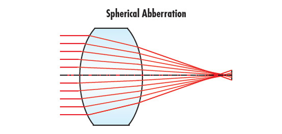
Telecentric lenses are often chosen for applications requiring demanding manufacturing measurements. Oftentimes, these applications include other challenges, such as limited WD ranges due to swinging robotic arms, contaminations nearby, or the existing mechanical layout of a machine into which the new measurement system must be fit. Like spacers, adding or removing shims at the rear of a telecentric lens takes advantage of the relationship between image distance, WD, and focal length (Figure 1) and adjusts the WD slightly into a usable range. In monochromatic applications, shims can also be used to compensate or refocus for chromatic focal shift (see Aberrations). Shims give users precise control of image distance to achieve the best possible solution for their application.
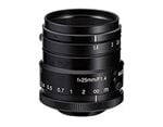
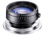
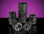
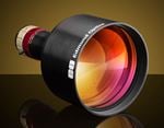
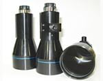
Focal Length Extenders/Multipliers
Another way to increase the magnification of a machine vision system is by using a focal length extender. A focal length extender is like a spacer in that they are both placed in between the back of the lens and the camera. However, a focal length extender will not change the WD range.
Focal length extenders contain a negative set of elements that change the focal length of a lens by a multiplicative factor. A 25mm focal length lens with a focal length extender of 2X will have an effective focal length of 50mm and will therefore halve the FOV at the same WD range. Focal length extenders can also be stacked upon one another and will have a multiplicative effect on the focal length of a lens. A 25mm focal length used with two focal length extenders of 1.5X and 2X will have a new focal length of 75mm.
In the same way spacers do not come without compromise, potential image quality reduction should be considered when using focal length extenders. Because the individual lens elements in an objective have all been collectively designed to balance optical performance, adding an additional negative element into the optical train will reduce performance by introducing additional optical aberrations. Focal length extenders also reduce the amount of light throughput in a lens by changing the f/#. A focal length extender of 2X will decrease light throughput by a factor of four. Effects on image quality must be considered before implementing a focal length extender.


or view regional numbers
QUOTE TOOL
enter stock numbers to begin
Copyright 2023, Edmund Optics Inc., 18 Woodlands Loop #04-00, Singapore 738100
California Consumer Privacy Act (CCPA): Do Not Sell or Share My Personal Information
California Transparency in Supply Chains Act