Engineers are available to assist.

|
|
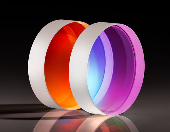
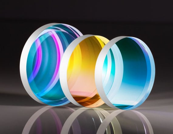
High reflectivity laser mirrors are critical components for beam steering |
|
|
The industry standard method of measuring reflectivity does not tell the whole story |
|
|
Reflectivity may seem simple but is actually a difficult value to measure |
|
|
Cavity ring down spectroscopy (CRDS) measures total loss in order to determine reflectivity |
High reflectivity mirrors, with reflectivity ranging from 99.8% up to 99.999%, are essential components in most laser systems for beam steering while maximizing throughput. It is common industry practice to determine mirror reflectivity by measuring transmission using spectrophotometry and assuming that the rest of the light was reflected. However, this false assumption does not consider scatter or absorption, leading to overly optimistic reflectivity values. For mirrors with reflectivities above 99.5%, a more accurate way to determine reflectivity is to measure total loss through cavity ring down spectroscopy (CRDS). Understanding your supplier’s metrology is critical for predicting real world performance.
It is standard industry practice for optical component suppliers to verify the reflectivity of mirrors by using a spectrophotometer to directly measure transmission. This assumes that scatter and absorption are insignificant but these smaller effects have a significant impact when very high reflectivity is required. Spectrophotometers can directly measure reflectivities below 99.5% but values higher than that reach the signal-to-noise ratio (SNR) limit of the spectrophotometer.
False Conclusion: ∑Intensity = Reflection + Transmission
Truth: ∑Intensity = Reflection + Transmission + Scatter + Absorption
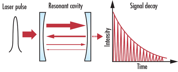
The most accurate metrology option for high reflectivity mirrors is cavity ring down spectroscopy (CRDS) which measures the total loss of the mirror, including transmission, absorption, and scatter. A laser pulse is introduced to a resonant cavity bounded by two highly reflective mirrors (Figure 1). The reflected laser light oscillates in the resonant cavity and a small amount of light is lost with each reflection. A detector placed after the second mirror measures the decreasing intensity of the reflected light. The total loss of the mirrors is determined by the decay time, or “ring down”, of the reflected light.
| I0: | initial laser pulse intensity |
| τ: | total cavity mirror loss |
| t: | time |
| c: | speed of light |
| L: | length of cavity |
The transmission of two high reflectivity mirrors was measured using transmission spectrophotometry (Figure 2). Mirror 2 had significantly lower measured transmission than Mirror 1, so it appears that Mirror 2 has a higher reflectivity. If no other metrology was done, it would be assumed that Mirror 1 has a nominal reflectivity of 99.9% and Mirror 2 has a nominal reflectivity of 99.99%.
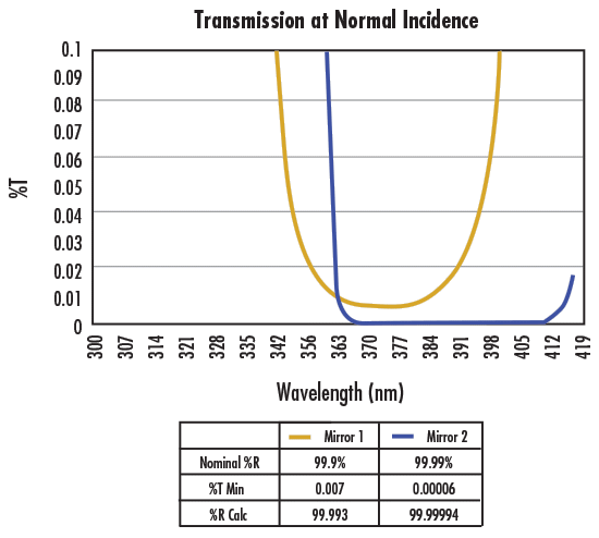
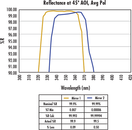
However, measuring both mirrors through CRDS reveals that this is not the case. The loss value of Mirror 1 was consistent with the nominal reflectivity determined using spectrophotometry, but the reflectance of Mirror 2 was so low that it could not even create resonance in the CRDS system. Measuring its reflectance directly by using reflectance spectrophotometry showed that Mirror 2 has much worse performance and a trailing reflectance that drops to 0.5% less than that of Mirror 1 due to absorption and scattering (Figure 3). The extra low reflectance at lower wavelengths is characteristic of absorption and scatter.
This example shows how critical it is to use the proper metrology technique for high reflectivity laser mirrors. Mirror 2 could lead to system failure if it was believed to have a reflectivity of 99.99%. In reality, it had a reflectance of 99.5%. This discrepancy between the test value and the true value can lead to performance degradation, safety issues, and even catastrophic system damage.
You can learn more about CRDS and high reflectivity mirrors for laser applications in this recorded webinar presented by Chris Cook, Tony Karam, Ian Stevenson, and Stefaan Vandendriessche.
Edmund Optics® utilizes CRDS to make highly sensitive loss measurements of both high reflectivity and high transmission optics. EO’s CRDS system is tuned for common Nd:YAG wavelengths and harmonics including 1064nm, 532nm, 355nm, and 266nm. The system can be tuned to other wavelengths upon request.
CRDS can only be used to measure mirrors with a reflectivity above 99.5% because lower reflectivities result in ring down times that are too fast for the system to detect. The best technique to determine reflectivity depends on the reflectivity level and application requirements.
Mirrors with reflectivities below 99.5% can be directly measured using reflection spectrophotometry. However, this technique will not work for mirrors with higher reflectivities because these systems reach the signal-to-noise ratio (SNR) limit.
Yes, absorption can be directly measured using photothermal deflection spectroscopy, in which measured changes in refractive index determine the amount of light absorption. scatter can be measured directly using a scatterometer or atomic force microscope (AFM). An AFM creates a highly accurate topological map of the sample and measures its roughness, which can then be used to calculate scatter.
Multiple tests must be completed with both the unknown test mirror and the reference mirrors in order to determine the loss of the test mirror.


or view regional numbers
QUOTE TOOL
enter stock numbers to begin
Copyright 2023, Edmund Optics Inc., 18 Woodlands Loop #04-00, Singapore 738100
California Consumer Privacy Act (CCPA): Do Not Sell or Share My Personal Information
California Transparency in Supply Chains Act