TECHSPEC® components are designed, specified, or manufactured by Edmund Optics. Learn More

Telecentric Backlight Illuminators

TECHSPEC® Telecentric Backlight Illuminators

×
  • Optically Collimated Light for Increased Edge Contrast
  • Superior Collimation Ideal for use with Telecentric Lenses
  • Easily Compatible with 8mm Coaxial LEDs or ¼” (0.312”) Fiber Light Guides
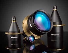
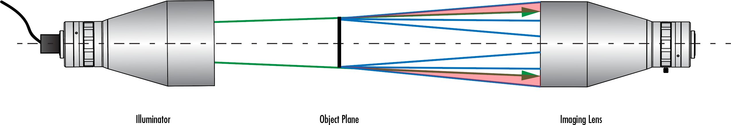
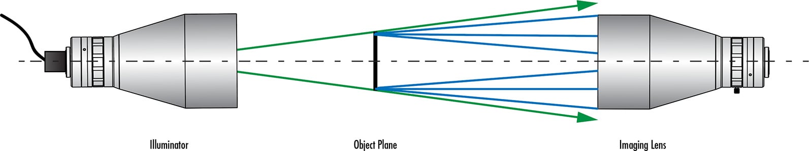
TECHSPEC® Telecentric Backlight Illuminators use the optical design principal of telecentricity to illuminate objects with truly collimated light and produce high contrast, silhouetted images. Standard backlights are diffuse to avoid hot spots, but these diffuse reflections can also reduce edge contrast. TECHSPEC® Telecentric Backlight Illuminators have collimated light rays (not diffuse) to increase edge contrast, thereby increasing measurement accuracy. Used in combination with a telecentric imaging lens, these illuminators are ideal for machine vision applications that require accurate measurements and are compatible with 8mm coaxial LEDS or ¼" (0.312") fiber optic light guides.

Note: Additional light source and light source power supply required for operation.

Technical Information

Technical Information


Why Use Telecentric Illumination?

  • Increased edge contrast compared to conventional backlight illumination
  • Ideal for precise measurement applications
  • Superior detection of small defects, measurement accuracy, and repeatability
  • Increased distance between illumination source and object
Clear Edge Silhouette from Telecentric Illuminator System
Blurry Edges from Standard Backlight System
Collimated Light Rays from a Telecentric Illuminator
Diffuse Reflections from a Standard Backlight
Figure 1: Comparison of the edge contrast achieved using telecentric illumination (left) and conventional backlighting (right). The collimated light rays from the telecentric illuminator lead to a high contrast silhouette while diffuse reflections from the standard backlight lead to blurred edges.


Importance of Numerical Aperture (NA) Matching

  • Matching the NA of your illumination source and imaging lens maximizes the efficiency of a system
  • Artificial vignetting is introduced if the illumination source NA is smaller than the imaging lens NA
  • Underfilling the imaging lens reduces contrast and results in a loss of object information
  • Overfilling the imaging lens throws away some light, but is preferable to underfilling
Underfilling occurs if the NA of the illumination source is smaller than the NA of the imaging lens, reducing contrast and resulting in loss of object information. Green lines represent the NA of the illumination source and blue lines represent the NA of the imaging lens.
Figure 2a: Underfilling occurs if the NA of the illumination source is smaller than the NA of the imaging lens, reducing contrast and resulting in loss of object information. Green lines represent the NA of the illumination source and blue lines represent the NA of the imaging lens.
Overfilling occurs if the NA of the illumination source is larger than the NA of the imaging lens, causing some light to be wasted. Overfilling is preferable than underfilling, but the NA’s should be as close as possible to reduce the amount of light loss.
Figure 2b: Overfilling occurs if the NA of the illumination source is larger than the NA of the imaging lens, causing some light to be wasted. Overfilling is preferable than underfilling, but the NA’s should be as close as possible to reduce the amount of light loss.