


How to Power USB and GigE Cameras: Choosing the Right Accessories
Authors: Gianna Riviello
Optimizing your imaging system means more than just choosing the right camera. Selecting the correct camera accessories ensures optimum performance, system stability, and successful integration. This application note explains power requirements for the two most common camera interfaces, USB and GigE, details the essential and optional accessories that enable reliable power delivery, and gives expert tips for selecting the most suitable components for your imaging system.
Understanding Power Options for USB and GigE Camera Interfaces
Choosing between the two main types of camera interfaces, Universal Serial Bus (USB) and Gigabit Ethernet (GigE), depends on several key factors including data transfer speed, system complexity and scalability, cost, and the physical distance between the camera and host PC. GigE cameras provide longer cable lengths and faster transfer rates compared to USB, while USB cameras offer a simpler “plug and play” setup with lower upfront costs. GigE can typically support Power-over-Ethernet (PoE) capability, meaning power and data transfer occur via ethernet using the same cable, with various configuration options. More detailed information on the advantages and disadvantages of each interface can be found in our Digital Camera Interfaces Guide. Powering your GigE or USB camera properly ensures that the system will function as intended. Below, different accessories for powering and optimizing camera setups are discussed.
Powering a USB Camera
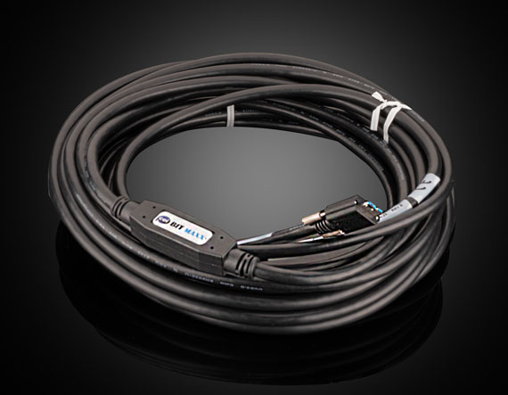
The USB CableSetting up a USB camera is straightforward—it only requires a USB cable that connects the camera to the computer’s USB port (Figure 1). This cable supplies power to the camera and transmits data to the computer.

Most computers are equipped with USB Type-A ports, which serve as the host-side connection. The type of USB connector on the camera—typically listed in its specifications—determines which cable is needed. A short overview of the USB connectors commonly available is given in Figure 2.
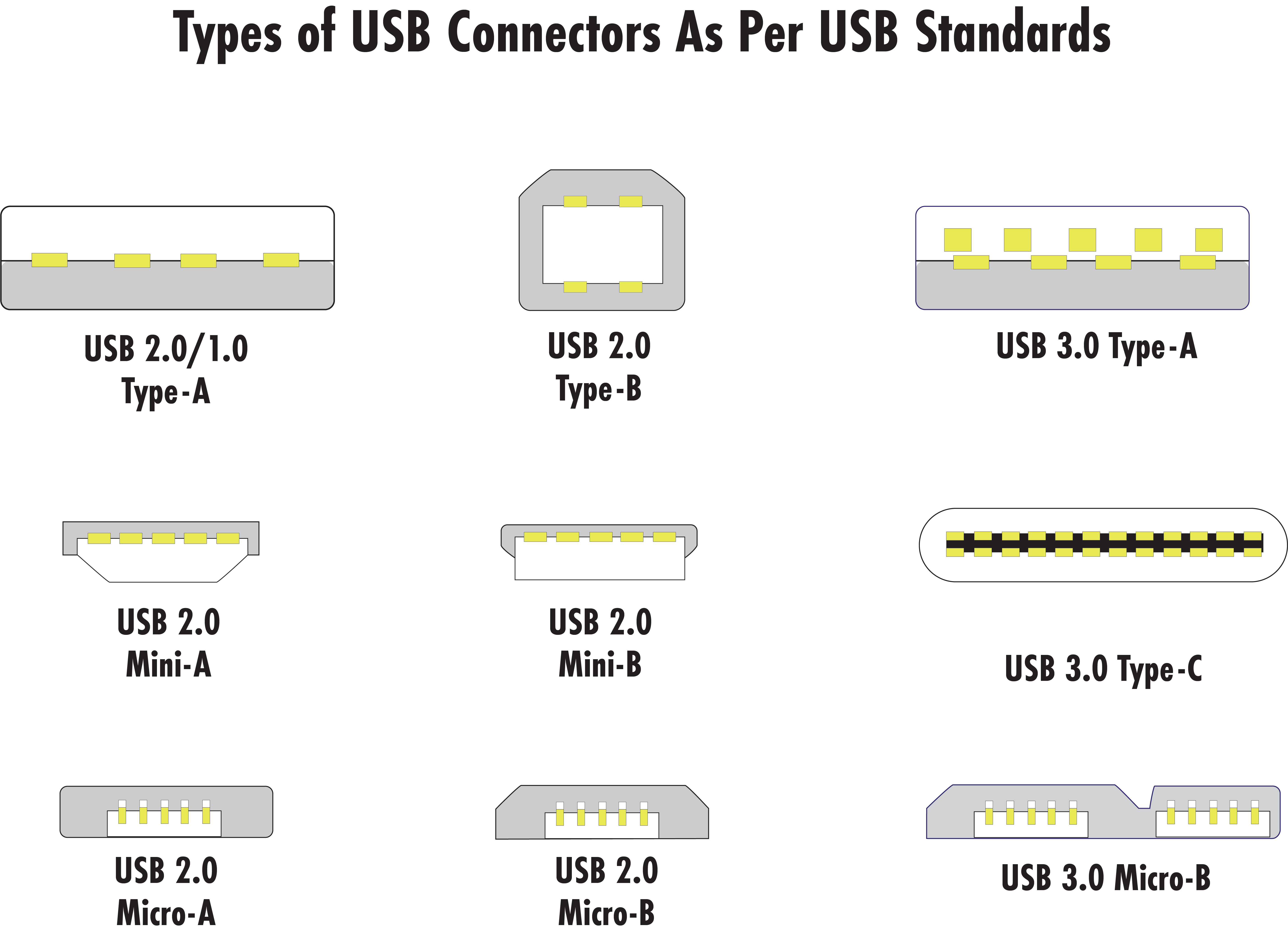
Always refer to the camera’s documentation to confirm the connector type before selecting a cable. For example, a camera with a USB Type-C connector will require a Type-A to Type-C cable, while one with a USB Micro-B would need a Type-A to Micro-B cable. When it comes to USB generations, the oldest generation defines the speed of the system. Therefore, it is best to match the generations when possible—e.g. using a USB 3.1 cable with a USB 3.1 camera. Although USB 2.0, 3.0, and 3.1 are backward compatible, data will transfer at the lower supported speed.
The USB Hub PortIn addition to limited cable length of only a few meters, the other limitation of USB is bandwidth. This means that, although multiple cameras can be connected to a PC using a USB Hub Port, they all would share the PC’s bandwidth. Figure 3 below shows a basic setup, where items in green are typically included with the hub port.

Powering a GigE Camera (PoE or Non-PoE)
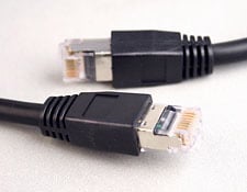
GigE cameras connect to a PC via ethernet. Unlike USB cables, ethernet cables can extend up to 100m and offer more flexible camera positioning. To ensure compatibility, the ethernet cable’s connector typically needs to match the camera’s connector. Commonly used connector types are RJ45 or M12 X-coded. The M12 connector is more robust and often used in harsh environments. It features a threaded locking option to withstand vibrations and offers better protection against dust and moisture. Widely used cable types for GigE cameras are Cat5e or Cat6. Cat5e is limited to smaller distances and cameras with 1Gbps. Longer distances as well as high resolutions and frame rates involve the use of Cat6. Most GigE camera setups require additional accessories beyond the ethernet cable. The following sections outline the available options.
GigE PoE Cameras
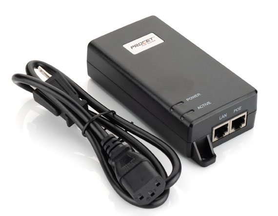
The PoE Port InjectorWhen running a single GigE camera with Power-over-Ethernet (PoE), a PoE port injector would be a simple and easy option to set up the system and provide power and data transfer through the same cable. The port injector has two ethernet ports: one camera connection port for connecting the injector to the camera, and one PC connection port connecting the injector to the PC. To complete the setup, two ethernet cables would need to be purchased. If not included with the device, the port injector requires its own power supply. No additional power source is needed for the camera, which can be a huge benefit in space-constrained applications. A typical PoE injector setup is shown in Figure 4. The port injector is the best option for lower cost, small footprint, and single camera systems.

When running multiple GigE cameras or even other ethernet devices, the PoE network switch allows for connecting multiple units on a local computer’s network. This setup maximizes available bandwidth per camera in multi-camera orientations. Each camera connects to the switch via a selected ethernet cable used for power and data transfer. An ethernet cable also runs from the computer to the switch. Just like the PoE port injector, the switch would also require its own external power supply if not already included. Figure 5 below shows a typical setup. While a PoE switch enables simultaneous multi-camera connectivity, keep in mind that limited network bandwidth can impact frame rates when many high-resolution or high-frame-rate cameras are connected.

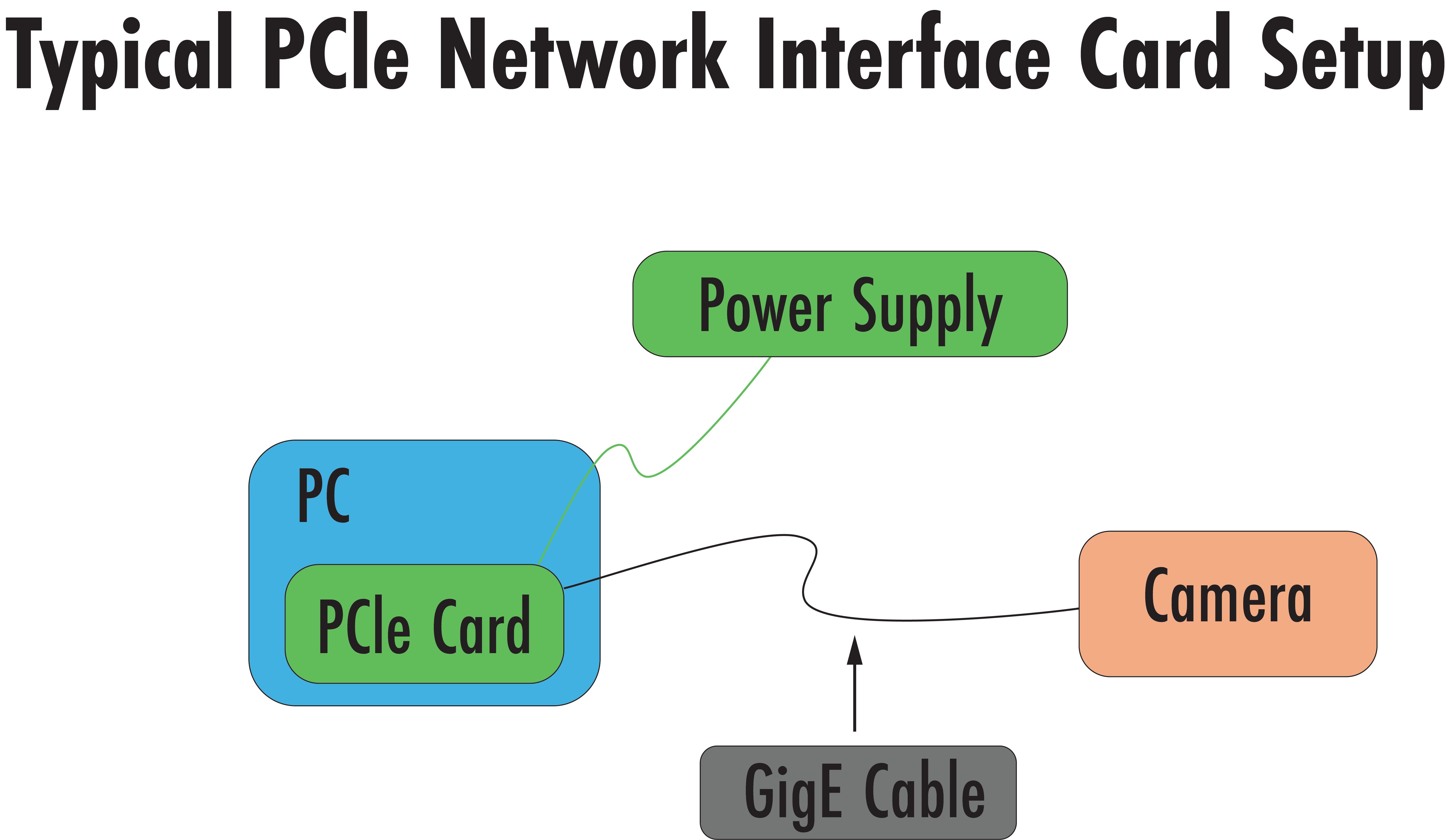
The Network Interface Card (NIC) connects to the Peripheral Component Interconnect Express (PCIe) slot of a PC to enhance the network performance of a PC. Similar to the network switch, it typically requires a separate power supply if not already included with the item, and ethernet cables would connect multiple GigE cameras to the card and are used for powering the camera and for data transfer. Up to 4 cameras can be connected to a PCIe card at once. Figure 6 shows a typical network interface card setup. Installing a card requires physically opening a PC to locate its PCIe slot, therefore it is important to understand if there are existing space constraints with a PC before purchasing.
If the selected camera is 2.5, 5, or 10GigE, or requires PoE+, be sure to choose a network interface card that matches the corresponding speed and supports PoE+ functionality. These cards are specifically designed to handle the higher bandwidths and power requirements of high-performance cameras and would be the most optimal way to power your camera.
GigE Non-PoE Cameras
The GPIOWhile GigE cameras are often powered using Power-over-Ethernet (PoE), they offer another option for providing power through the General-Purpose Input/Output (GPIO) connector, sometimes also referred to as an I/O connector. For cameras without PoE functionality, the GPIO port serves as the primary power input. In this configuration, power is supplied by an external power supply, not through the ethernet cable. This is ideal for systems where space is limited and efficient power usage with minimal heat generation and low cable transmission losses are essential. The setup would still require the ethernet cable for data transfer, but no PoE device, such as a port injector, is needed (see Figure 7 below). If you are using external devices like trigger hardware, they are also typically connected via the GPIO port. If such hardware is used, the GPIO connector may no longer be available for supplying power to the camera. In this case, the power has to be supplied via a PoE port injector or a cable with flying leads should be considered to provide both power and the trigger signal through separate leads. Hardware options are listed under the “Specifications” tab for each camera if available.

Overview of Power Accessories for USB and GigE Cameras
Table 1 provides a quick summary of the power accessories mentioned in the text above. It highlights the products and options you can use for your imaging systems and also gives some basic information to facilitate your decision.
| Difficulty of Assembly | Cost | Number of Devices Supported | |
|---|---|---|---|
| USB Cable | Easy—Plug and play, provides power and data transfer | Low | 1 |
| GigE Port Injector | Easy—Plug and play with additional wall powered component | Low | 1 |
| GigE Network Switch | Medium—Requires network setup and cabling | Medium | 4+ |
| GigE PCIe Card | Hard—Requires opening PC case and installing card and drivers | High | 1-4 |
| GPIO Power Supply | Easy—Plug into wall power, data cable required | Low | 1 |


References
- Teledyne Vision Solutions. (2015, May 4). Machine Vision Interface Comparison and Evolution: Getting the most out of Integrated Imaging Solution’s USB 3.1 cameras [White paper]. Teledyne Vision Solutions. https://www.teledynevisionsolutions.com/support/support-center/whitepaper/iis/machine-vision-interface-comparison-and-evolution/
- Edmund Optics Inc. Camera Types and Interfaces for Machine Vision Applications. In Imaging Resource Guide: Cameras, Section 10.1. Edmund Optics. https://www.edmundoptics.com/knowledge-center/application-notes/imaging/camera-types-and-interfaces-for-machine-vision-applications/
- OnLogic. What is PoE (Power over Ethernet)? OnLogic Blog. https://www.onlogic.com/blog/what-is-poe-power-over-ethernet/
- LUCID Vision Labs. (Aug 29, 2024). Powering a Machine Vision Camera [Video]. YouTube. https://www.youtube.com/watch?v=CKMWnZZWHbI
More Resources
- Digital Camera Interfaces Application Note
- What is Imaging? Application Note
- Imaging Electronics 101: Understanding Camera Sensors for Machine Vision Applications Application Note
- Imaging Electronics 101: Basics of Digital Camera Settings for Improved Imaging Results Application Note
- Imaging Electronics 101: Camera Resolution for Improved Imaging System Performance Application Note
or view regional numbers
QUOTE TOOL
enter stock numbers to begin
Copyright 2024, Edmund Optics Singapore Pte. Ltd, 18 Woodlands Loop #04-00, Singapore 738100
California Consumer Privacy Acts (CCPA): Do Not Sell or Share My Personal Information
California Transparency in Supply Chains Act
This content may include material that has been generated or modified using artificial intelligence (AI).
The FUTURE Depends On Optics®