


Laser Beam Shaping Overview
This is Sections 5.1, 5.2, 5.3, 5.4, 5.5, and 5.6 of the Laser Optics Resource Guide.
A laser beam shape is typically defined by its irradiance distribution and phase. The latter is essential in determining the uniformity of a beam profile over its propagation distance. Therefore, beam shapers are designed to redistribute the irradiance and phase of an optical beam to attain a desired beam profile that is maintained along the desired propagation distance. Common irradiance distributions include Gaussian, in which irradiance decreases with increasing radial distance, and flat top beams, also known as top hat beams, in which irradiance is constant over a given area (Figure 1). A detailed description of Gaussian beam propagation can be found in our Gaussian Beam Propagation application note and information on quantifying the quality of a laser’s irradiance distribution can be found in our Laser Resonator Modes application note.
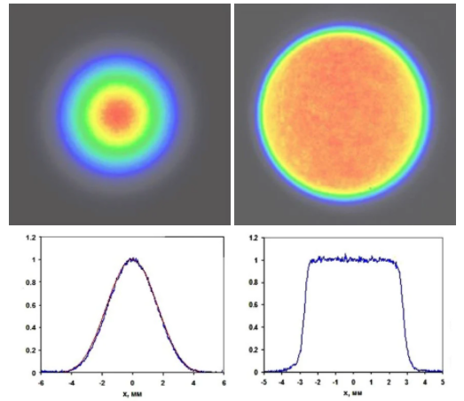
Figure 1: For a Gaussian beam profile (left), irradiance decreases with increasing distance from the center according to a Gaussian equation. For a flat top beam (right), irradiance is constant over a given area.
Some applications benefit from beam profiles different from that of the laser source, which is typically Gaussian. For example, flat top profiles are advantageous in applications such as certain materials processing systems because they often result in more accurate and predictable cuts and edges than Gaussian beams (Figure 2). However, introducing a beam-shaping optics increases system complexity and cost.
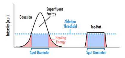
Figure 2: Beams with Gaussian profiles are less efficient than those with flat top profiles in laser ablation applications because of both a large beam area with superfluous energy higher than the required ablation threshold and energy lower than the threshold in the outer regions of the Gaussian profile.
Beam shaping modifies the properties of light at their most fundamental level and its efficiency is determined by Heisenberg uncertainty principle on time-bandwidth:1
x represents position and v represents momentum. The uncertainty principle adds some limitations to the design of beam shapers. For example, for a design with very well-defined position, the spatial frequencies become less defined. Applying the uncertainty principle to diffraction theory, i.e. the Fourier transform relation in the Fresnel integral, a characteristic parameter $ \beta $ is obtained:
where $ \small{r_o} $ is the input beam half-width, $ \small{r_i} $ is the output beam half-width, $ \small{C} $ is a constant, $ \small{\lambda} $ is the wavelength, and $ \small{z} $ is the distance to the output plane. The value of $ \small{\beta} $ is very important when designing or considering a beam shaping application since larger values correspond with better beam shaping performance. For example, for $ \small{\beta} < 4 $, the beam shaper will not produce acceptable results for essentially any laser application, while a $ \small{ 4 < \beta <16} $ would provide low performance. Hence, for optimal performance, experimental conditions that lead to $ \small{\beta} > 16 $ should be employed. This formula implies that it will be more straightforward to design beam shapers for larger beams, shorter wavelengths, and shorter focus distances.
Refractive Beam Shaping
In low-performance systems where cost is a driving factor, Gaussian beams may be physically truncated by an aperture to form a pseudo-flat top profile. This is inefficient and wastes the energy in the outer regions of the Gaussian profile, but it minimizes system complexity and cost.
Higher-performance applications requiring more efficiency often employ either refractive and diffractive laser beam shapers. These assemblies typically utilize field-mapping phase elements, such as aspheric or freeform lenses and diffractive elements, to redistribute the irradiance and phase profile of laser light. Figure 3 shows an example layout of a refractive field mapper that transforms a Gaussian beam profile to a flat top profile through wavefront distortion and the energy conservation condition.2 The amplitude and phase of the incident beam are changed after passing through both elements in a Galilean or Keplerian lens assembly. The resulting beam shaping is highly efficient (>96% throughput) and wavelength-independent within the range of the design. Refractive beam shapers allow for uniform irradiance distribution and flat phase fronts.
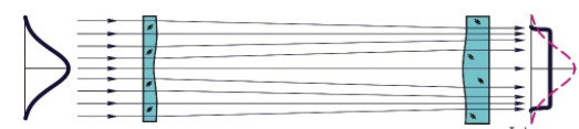
Figure 3: Example of refractive beam shaping employing field mapping2
However, focusing a flat top beam through a lens will not result in a flat top profile at the final focused spot, as the lens will affect the beam profile. When a flat top focused spot is desired, field mappers are instead used to convert Gaussian beams to collimated Airy disk profiles, which form flat top spots after being focused by a diffraction-free lens (Figure 4).
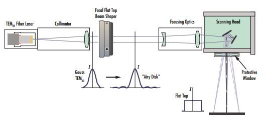
Figure 4: Depiction of how some beam shapers, such as the AdlOptica Focal-πShaper Q Flat Top Beam Shaper, convert incident Gaussian beam profiles into airy disk profiles so that they result in flat top beam profiles after transmitting through focusing optics.
Diffractive Beam Shaping
Diffractive beam shapers utilize diffraction, rather than refraction, to shape the laser beam into a specific irradiance distribution. Diffractive elements employ an etching process to create a specific micro- or nanostructure in a substrate. Typically, the design wavelengths and function of the element are dependent on the height and zone spacing, respectively. Hence, using a diffractive optical element at the design wavelength is essential in order to avoid performance errors. Compared to refractive beam shapers, diffractive elements are also more dependent on alignment, divergence, and the beam position in the plane of the nominal working distance. On the other hand, diffractive optical elements are very advantageous in space-limited laser setups since they are usually made of a single element, rather than multiple refractive lenses.
Laser Beam Integrators
A laser beam integrator, or homogenizer, is composed of multiple Ienslets that divide the beam into an array of smaller beams, or beamlets, followed by a lens or other focusing element that superimposes the beamlets at the target plane. They can be used with both coherent laser light and other incoherent light sources. Typically, the final output beam profile is the sum of the diffraction patterns determined by the lenslet array. Most laser beam integrators are used to generate a homogenized flat top profile from incident Gaussian beams. Beam homogenizers usually suffer from random irradiance fluctuations, which leads to beam profile that is not perfectly flat. Non-diffraction-based beam integrators, such as imaging integrators or waveguides, are also suitable for spatially incoherent incident light. The choice between diffraction or imaging beam integrators depends on the Fresnel number. As a rule of thumb, for Fresnel numbers <10, an imaging integrator will be needed to obtain a highly uniform flat top profile.3
| Refractive | Diffractive | Beam integrators | |
| Shaping principle | Deterministic | Deterministic | Random or quasi-random |
| Random fluctuations | Low | Low | High |
| Alignment sensitivity | Low | Low | High |
| Output beam uniformity | High | Medium-high | Low |
| Cost | High | Medium | Low |
| Footprint | Large | Small | Small |
Table 1: This table compares different technologies for laser beam shaping.
Axicons for Generating Bessel Beams
So far, we have discussed shaping light using field mapping or beam integration where diffraction effects play major roles in the design and performance of the optics. Diffraction is the deviation of light from propagating in a straight line that is not caused by reflection or refraction. These diffraction effects cause laser beams to diverge as they propagate. On the other hand, a beam whose profile is described by a Bessel function, which is defined as the exact and invariant solution of the Helmholtz equation, does not experience diffraction; i.e. it does not spread out as it propagates.4 These beams are also self-healing, which means that they can reform at any point after obstruction. However, ideal Bessel beams are impossible to generate because they would require an infinite amount of energy. Instead, approximate Bessel beams knowns as quasi-Bessel beams can be generated by interference of plane waves formed by a conical surface such as an axicon.
Axicons form a quasi-Bessel beam with nearly zero diffraction over a given region, known as their depth-of-field (DOF). After this region, the beam continues propagating in a ring-like pattern (Figure 5). Traditional, refractive axicons are considered either conical lenses or prisms. Light transmits through them and then refracts at the conical surface. Reflective axicons with a reflective conical surface are also employed in certain situations such as ultrafast laser systems. The broad wavelength bandwidth inherent to ultrafast lasers would experience significant chromatic dispersion transmitting through a refractive axicon, while this dispersion is avoided in reflective axicons (Figure 6). Quasi-Bessel beams can also be generated using holographic methods with high diffraction efficiencies but suffer from a diffraction-modulated axial profile.
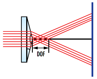
Figure 5: Schematic of a traditional refractive axicon showing the Bessel beam region in the DOF and the ring-shaped beam that propagates after the overlap region.
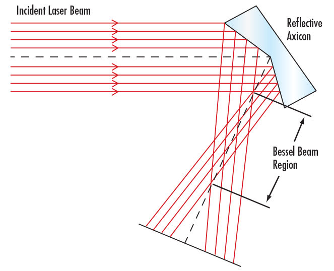
Figure 6: Schematic of a reflective axicon which, like the traditional axicon, creates a Bessel beam region in the DOF and a ring-shaped beam after the overlap region but, unlike traditional axicons, is independent of wavelength.
Bessel beams experience little to no diffraction within their propagation distance and provide an excellent DOF, which makes them ideal for applications such as laser material processing and corneal surgery. Clean cuts with sharp edges can be generated in the DOF because of the uniform beam diameter.
Circularizing Beams with Cylinder Lenses
Another type of laser beam shaping is circularizing a beam, which involves converting an oval or differently shaped profile to a circular one. Laser diodes with no collimating optics will have different divergence angles in the x- and y-axes because of the rectangular shape of the diode’s active region, resulting in oblong beam shapes (Figure 7). Circular profiles are often desired to form symmetric, compact final focused spots.
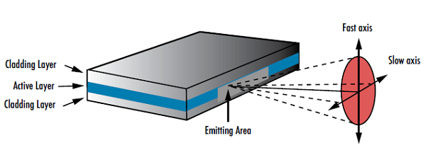
Figure 7: The geometry of laser diodes causes them to produce elliptical beams with two different divergence angles
Like standard spherical lenses, cylinder lenses use curved surfaces to converge or diverge light, but they only have optical power in one dimension. Cylinder lenses do not affect light in the perpendicular dimension. This cannot be achieved using standard spherical lenses because light will focus or diverge uniformly in a rotationally symmetric manner. This property of cylinder lenses makes them useful for forming laser light sheets and circularizing elliptical beams.
The reference system of cylinder lenses is defined by two orthogonal dimensions: the power direction and the non-power direction. The “power direction” runs along the curved length of the lens and is the only axis of the lens with optical power (Figure 8). The “non-power direction” of the cylinder lens runs along the length of the lens without any optical power. The cylinder lens’ length along the non-power direction can vary without affecting the lens’ optical power. Cylinder lenses can have a variety of form factors including rectangular, square, circular, and elliptical shapes.
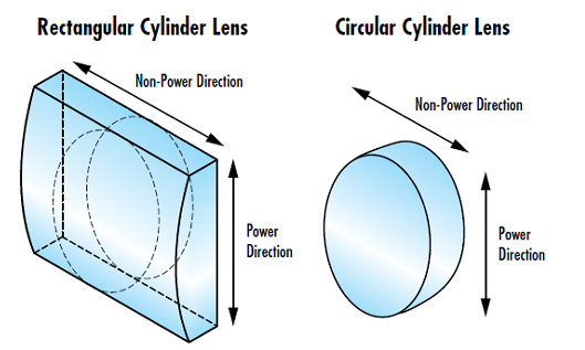
Figure 8: Power and non-power directions in both rectangular and circular cylinder lenses
Because laser diodes diverge in an asymmetrical pattern, a spherical optic cannot be used to produce a circular collimated beam from a diode. The lens acts on both axes at the same time, which maintains the original asymmetry in the beam. Each axis can be treated separately using an orthogonal pair of cylinder lenses.
The ratio of both lenses’ focal lengths should match the ratio of the x and y beam divergences in order to achieve a symmetrical output beam. Similar to standard collimation, the laser diode is placed at the shared focal point of both lenses and the distance between the lenses is kept equal to the difference of their focal lengths (Figure 9).
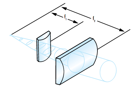
Figure 9: Example of circularizing an elliptical beam using cylinder lenses.
The small output apertures of laser diodes may lead to very large divergence angles, which can be challenging when trying to collimate the beam. Divergence has a direct effect on both the allowable length of the system and the required sizes of the lenses. The relationship between divergence and beam size is described in our Gaussian Beam Propagation application note. Because the relative positions of each cylinder lens are fairly fixed based on their focal length, it is possible to calculate the maximum beam width $ \left( \small{d} \right) $ at each lens using the focal length of the lens $ \left( \small{f} \right) $ and the divergence angle $ \left( \small{\theta} \right) $ of the axis that the lens is collimating. Each lens’ clear aperture must then be larger than the corresponding maximum beam width to avoid clipping the beam.
For more information, please visit our Considerations When Using Cylinder Lenses application note.
Circularizing Beams with Anamorphic Prism Pairs
Anamorphic prism pairs are other types of optics used for circularizing elliptical beams. Anamorphic prism pairs consist of two prisms used together to reshape a laser beam. They are typically used to change elliptical beam profiles into circular distributions, but they can also produce other elliptical beam profiles in a variety of sizes. The optical principle at play behind the reshaping is the same as that of cylinder lenses: refraction. Light is bent in one direction, or one axis, while the other axis remains constant (Figure 10). This compensates for the beam’s different divergence angles.
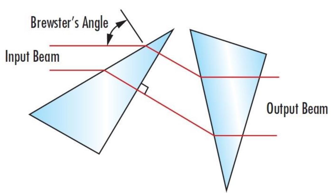
Figure 10: An anamorphic prism pair acting as a beam expander in one direction, which can circularize an elliptical beam.
A lone prism could change the beam radius in a single axis, but this would also change the beam direction. Two prisms are required to maintain the beam’s original direction of propagation while manipulating its ellipticity. Anamorphic prism pairs maintain parallelism to the original direction, but they do displace the beam in the perpendicular direction. Using anamorphic prism pairs also requires precise angular alignment for proper functioning. It is not required, but it is useful for one prism to be oriented at Brewster’s angle, or the angle of incidence where there is no reflection of p-polarized light. The other surface of the prism would be at normal incidence to the beam and should be anti-reflection (AR) coated to maximize throughput. The precise alignment required leads many optical system integrators to buy them as a pre-aligned pair.
High-end laser diodes often have anamorphic prism pairs built into their laser head to circularize beams. Many lower cost diodes, however, do not. The cost of purchasing a separate anamorphic prism pair and a less-expensive diode lacking an integrated anamorphic prism pair can be less than that of a more expensive diode.
Cylinder lenses have more degrees of freedom than mounted anamorphic prism pairs, which makes them more challenging to align. Cylinder lenses can tilt, which makes anamorphic prisms more forgiving when attempting to align axes independently. Careful attention must also be paid to the focal length of cylinder lenses so that they are placed the correct distance away from the laser diode to produce a collimated, circularized output beam. Mounted anamorphic prism pairs are more user friendly. They are pre-aligned to a fixed expansion power, so eliminating the need to position and assemble them yourself like you would have to do with cylinder lenses. The prisms only have a single axis which must be independently aligned because the user is merely sliding the prism into the beam path. This removes an alignment step, saving the user both time and potential frustration. The physical location of the anamorphic prisms, relative to the incident laser beam’s location, is also less sensitive.
However, the extra degrees of freedom offered by cylinder lenses result in more flexibility, which might be useful in research settings and prototyping. Cylinder lenses can also provide higher throughput than anamorphic prism pairs, especially when the lenses feature AR coatings. Light does not need to travel through as much material in cylinder lenses compared to anamorphic prism pairs, and p-polarized light will be lost if anamorphic prisms are used at Brewster’s angle. For more information, please visit our Anamorphic Prism Pairs application note.
| Cylinder Lenses | Anamorphic Prism Pairs | |
| Beam displacement | Not displaced | Displaced |
| Degrees of freedom | High | Low |
| Alignment sensitivity | High | Low |
| Throughput | High | Medium |
| Cost | Low | Low |
| Footprint | Small | Small |
Table 2: Comparison of cylinder lenses and anamorphic prism pairs for beam circularization.
References:
- F. M. Dickey and S. C. Holswade, Laser Beam Shaping: Theory and Techniques, Marcel Dekker, New York (2000).
- Laskin, Alexander, and Vadim Laskin. "Refractive field mapping beam shaping optics: important features for a right choice." Proc. ICALEO. Vol. 2010. (2010).
- F.M. Dickey, S.C. Hoswade, D.L. Shealy, Laser Beam Shaping Applications, Taylor & Francis, ISBN 0-8247-5941 (2005).
- J. Durnin: J. Opt. Soc. Am. A 4 (1987) 651.
More Resources
- Why Use a Flat Top Laser Beam?
- An In-Depth Look at Axicons
- Reflective Laser Beam Shaping
- Considerations when Using Cylinder Lenses
- Anamorphic Prism Pairs
- Laser Resonator Modes
- Aligning Mount for AdlOptica Beamshapers
- Aligning AdlOptica πShaper
- Aligning AdlOptica Focal πShaper
- Why Choose an Achromatic Cylinder Lens?
- What are Cylinder Lenses?
- Laser Optics Lab Video Series


or view regional numbers
QUOTE TOOL
enter stock numbers to begin
Copyright 2024, Edmund Optics Singapore Pte. Ltd, 18 Woodlands Loop #04-00, Singapore 738100
California Consumer Privacy Acts (CCPA): Do Not Sell or Share My Personal Information
California Transparency in Supply Chains Act
This content may include material that has been generated or modified using artificial intelligence (AI).
The FUTURE Depends On Optics®